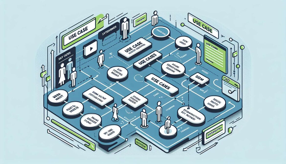
Use Case diagrams serve as the crucial bridge between business requirements and technical design, capturing system functionality from the user’s perspective. Unlike class diagrams that show internal structure or object diagrams that show runtime instances, Use Case diagrams focus on what the system does for its users—the external view that drives all internal design decisions.
In this fourth part of our UML series, we’ll master the art of capturing user requirements, modeling system boundaries, and translating business needs into actionable development requirements.
Understanding Use Case Fundamentals
Use Case diagrams consist of three primary elements that work together to define system functionality:
- Actors: External entities that interact with the system (users, other systems, devices)
- Use Cases: Specific functionality or services the system provides
- System Boundaries: The scope and limits of the system being modeled
Basic Use Case Diagram Structure
Here’s a simple e-commerce system to demonstrate the fundamental elements:
flowchart TD
    subgraph System["E-commerce System"]
        UC1[Browse Products]
        UC2[Add to Cart]
        UC3[Checkout]
        UC4[Process Payment]
        UC5[Manage Inventory]
        UC6[Generate Reports]
    end

    Customer((Customer))
    Admin((Admin))
    PaymentGateway((Payment Gateway))

    Customer --> UC1
    Customer --> UC2
    Customer --> UC3
    Admin --> UC5
    Admin --> UC6
    UC4 --> PaymentGateway
Actors: Who Interacts with Your System?
Actors represent anyone or anything that interacts with your system from the outside. Identifying actors correctly is crucial for complete requirements capture.
Types of Actors
- Primary Actors: Initiate interactions to achieve goals (customers, employees)
- Secondary Actors: Provide services to the system (payment processors, email services)
- System Actors: Other software systems that interact with yours
flowchart TD
    subgraph LMS["Learning Management System"]
        UC1[Enroll in Course]
        UC2[Submit Assignment]
        UC3[Grade Assignment]
        UC4[Generate Transcript]
        UC5[Process Payment]
        UC6[Send Notifications]
    end

    Student((Student))
    Instructor((Instructor))
    Admin((Administrator))
    PaymentSystem((Payment System))
    EmailSystem((Email System))

    Student --> UC1
    Student --> UC2
    Instructor --> UC3
    Admin --> UC4
    UC5 --> PaymentSystem
    UC6 --> EmailSystem
Use Case Relationships
Use cases can have relationships with each other that help organize and clarify system functionality:
Include Relationships
Include relationships show when one use case always incorporates another use case’s functionality:
flowchart TD
    subgraph OnlineBanking["Online Banking System"]
        UC1[Transfer Money]
        UC2[Validate User]
        UC3[Check Account Balance]
        UC4[Log Transaction]
        UC5[Send Confirmation]
    end

    Customer((Customer))

    Customer --> UC1
    UC1 -. includes .-> UC2
    UC1 -. includes .-> UC3
    UC1 -. includes .-> UC4
    UC1 -. includes .-> UC5
Extend Relationships
Extend relationships show optional functionality that may be added under certain conditions:
flowchart TD
    subgraph ATM["ATM System"]
        UC1[Withdraw Cash]
        UC2[Print Receipt]
        UC3[Check Balance]
        UC4[Apply Overdraft]
        UC5[Charge Fee]
    end

    BankCustomer((Bank Customer))

    BankCustomer --> UC1
    BankCustomer --> UC3
    UC2 -. extends .-> UC1
    UC4 -. extends .-> UC1
    UC5 -. extends .-> UC1
Generalization Relationships
Generalization shows inheritance between actors or use cases:
flowchart TD
    subgraph CRM["Customer Relationship Management"]
        UC1[Manage Contacts]
        UC2[View Customer Data]
        UC3[Edit Customer Data]
        UC4[Delete Customer Data]
        UC5[Generate Reports]
        UC6[Approve Changes]
    end

    User((User))
    SalesRep((Sales Rep))
    Manager((Manager))

    SalesRep --> User
    Manager --> User

    User --> UC1
    User --> UC2
    SalesRep --> UC3
    Manager --> UC4
    Manager --> UC5
    Manager --> UC6
Real-World Example: Hospital Management System
Let’s create a comprehensive use case diagram for a hospital management system to demonstrate complex actor relationships and system boundaries:
flowchart TD
    subgraph HMS["Hospital Management System"]
        subgraph PatientCare["Patient Care"]
            UC1[Schedule Appointment]
            UC2[Register Patient]
            UC3[Conduct Examination]
            UC4[Prescribe Medication]
            UC5[Order Lab Tests]
        end

        subgraph Administration["Administration"]
            UC6[Manage Staff]
            UC7[Generate Bills]
            UC8[Process Insurance]
            UC9[Maintain Records]
            UC10[Generate Reports]
        end

        subgraph Pharmacy["Pharmacy"]
            UC11[Dispense Medication]
            UC12[Check Drug Interactions]
            UC13[Update Inventory]
        end
    end

    Patient((Patient))
    Doctor((Doctor))
    Nurse((Nurse))
    Administrator((Administrator))
    Pharmacist((Pharmacist))
    InsuranceCompany((Insurance Company))
    LabSystem((Lab System))

    Patient --> UC1
    Patient --> UC2
    Doctor --> UC3
    Doctor --> UC4
    Doctor --> UC5
    Nurse --> UC3
    Administrator --> UC6
    Administrator --> UC7
    Administrator --> UC8
    Administrator --> UC9
    Administrator --> UC10
    Pharmacist --> UC11
    Pharmacist --> UC12
    Pharmacist --> UC13
    UC8 --> InsuranceCompany
    UC5 --> LabSystem
Writing Effective Use Case Descriptions
While use case diagrams provide the visual overview, detailed use case descriptions capture the step-by-step flow. Here’s a template for documenting use cases:
Use Case: Process Online Order
Actor: Customer
Preconditions: Customer is logged in, has items in cart
Main Flow:
1. Customer initiates checkout
2. System displays order summary
3. Customer confirms delivery address
4. Customer selects payment method
5. System processes payment
6. System confirms order and sends confirmation email
7. System updates inventory
8. System notifies fulfillment center

Alternative Flows:
- Payment failure: Return to payment selection
- Inventory insufficient: Remove unavailable items
- Address invalid: Prompt for address correction

Postconditions: Order is created, payment processed, inventory updated
Use Case Modeling Best Practices
Identifying Use Cases
Look for these patterns when identifying use cases:
- User Goals: What does each actor want to accomplish?
- System Services: What functions must the system provide?
- Business Processes: What workflows need to be supported?
- External Triggers: What events cause system responses?
Use Case Granularity
Finding the right level of detail is crucial:
- Too High-Level: “Manage E-commerce” (not actionable)
- Just Right: “Process Customer Order” (clear, achievable goal)
- Too Detailed: “Validate Credit Card CVV” (implementation detail)
Advanced Use Case Patterns
Multi-System Integration
Modern systems often integrate with multiple external systems. Here’s how to model these complex relationships:
flowchart TD
    subgraph TravelApp["Travel Booking System"]
        UC1[Search Flights]
        UC2[Book Flight]
        UC3[Reserve Hotel]
        UC4[Rent Car]
        UC5[Process Payment]
        UC6[Send Confirmation]
        UC7[Check Flight Status]
    end

    Traveler((Traveler))
    Agent((Travel Agent))
    AirlineAPI((Airline API))
    HotelAPI((Hotel API))
    CarRentalAPI((Car Rental API))
    PaymentGateway((Payment Gateway))
    EmailService((Email Service))

    Traveler --> UC1
    Traveler --> UC2
    Traveler --> UC3
    Traveler --> UC4
    Agent --> UC2
    Agent --> UC3

    UC1 --> AirlineAPI
    UC2 --> AirlineAPI
    UC3 --> HotelAPI
    UC4 --> CarRentalAPI
    UC5 --> PaymentGateway
    UC6 --> EmailService
    UC7 --> AirlineAPI
Role-Based Access Control
Use case diagrams effectively model systems with different user roles and permissions:
flowchart TD
    subgraph ProjectManagement["Project Management System"]
        subgraph BasicFeatures["Basic Features"]
            UC1[View Projects]
            UC2[View Tasks]
            UC3[Update Task Status]
        end

        subgraph TeamLeadFeatures["Team Lead Features"]
            UC4[Create Projects]
            UC5[Assign Tasks]
            UC6[Review Progress]
        end

        subgraph AdminFeatures["Admin Features"]
            UC7[Manage Users]
            UC8[Configure System]
            UC9[Generate Reports]
            UC10[Backup Data]
        end
    end

    TeamMember((Team Member))
    TeamLead((Team Lead))
    Administrator((Administrator))

    TeamMember --> UC1
    TeamMember --> UC2
    TeamMember --> UC3

    TeamLead --> UC1
    TeamLead --> UC2
    TeamLead --> UC3
    TeamLead --> UC4
    TeamLead --> UC5
    TeamLead --> UC6

    Administrator --> UC7
    Administrator --> UC8
    Administrator --> UC9
    Administrator --> UC10
Use Case Scenarios and Extensions
Complex use cases often have multiple scenarios and exception flows:
flowchart TD
    subgraph OnlineStore["Online Shopping System"]
        UC1[Place Order]
        UC2[Validate Payment]
        UC3[Apply Discount]
        UC4[Handle Payment Failure]
        UC5[Check Inventory]
        UC6[Notify Out of Stock]
        UC7[Calculate Shipping]
    end

    Customer((Customer))
    PaymentProcessor((Payment Processor))
    InventorySystem((Inventory System))

    Customer --> UC1
    UC1 -. includes .-> UC2
    UC1 -. includes .-> UC5
    UC1 -. includes .-> UC7
    UC3 -. extends .-> UC1
    UC4 -. extends .-> UC2
    UC6 -. extends .-> UC5

    UC2 --> PaymentProcessor
    UC5 --> InventorySystem
From Use Cases to System Design
Use case diagrams drive many other UML diagrams and system design decisions:
Traceability Matrix
Use cases connect to other design artifacts:
- Sequence Diagrams: Show how use cases are implemented through object interactions
- Class Diagrams: Define the objects needed to support use cases
- Activity Diagrams: Detail the workflow within complex use cases
API Design from Use Cases
Use cases translate directly to API endpoints and system interfaces:
// Use Case: "Place Order" becomes:
POST /api/orders
{
  "customerId": "CUST-001",
  "items": [
    {"productId": "PROD-001", "quantity": 2},
    {"productId": "PROD-002", "quantity": 1}
  ],
  "shippingAddress": {...},
  "paymentMethod": {...}
}

// Use Case: "Track Order" becomes:
GET /api/orders/{orderId}/status

// Use Case: "Cancel Order" becomes:
DELETE /api/orders/{orderId}
Mobile App Use Case Example
Let’s model a fitness tracking mobile app to show how use cases work with modern applications:
flowchart TD
    subgraph FitnessApp["Fitness Tracking App"]
        subgraph Core["Core Features"]
            UC1[Track Workout]
            UC2[Log Nutrition]
            UC3[Set Goals]
            UC4[View Progress]
        end

        subgraph Social["Social Features"]
            UC5[Share Achievement]
            UC6[Follow Friends]
            UC7[Join Challenges]
        end

        subgraph Premium["Premium Features"]
            UC8[Get Personal Plan]
            UC9[Video Coaching]
            UC10[Advanced Analytics]
        end
    end

    FreeUser((Free User))
    PremiumUser((Premium User))
    Trainer((Trainer))
    HealthDevice((Health Device))
    SocialMedia((Social Media))

    FreeUser --> UC1
    FreeUser --> UC2
    FreeUser --> UC3
    FreeUser --> UC4
    FreeUser --> UC5
    FreeUser --> UC6

    PremiumUser --> UC1
    PremiumUser --> UC2
    PremiumUser --> UC3
    PremiumUser --> UC4
    PremiumUser --> UC5
    PremiumUser --> UC6
    PremiumUser --> UC7
    PremiumUser --> UC8
    PremiumUser --> UC9
    PremiumUser --> UC10

    Trainer --> UC8
    Trainer --> UC9

    UC1 --> HealthDevice
    UC5 --> SocialMedia
Use Case Documentation Templates
Effective use case documentation follows consistent templates that capture all necessary information:
Use Case ID: UC-001
Use Case Name: Track Daily Workout
Actor: Fitness App User
Description: User records exercise session with duration, type, and intensity

Preconditions:
- User is logged into the app
- User has started a workout session

Main Success Scenario:
1. User selects "Start Workout"
2. System displays exercise types
3. User selects exercise type
4. User starts timer
5. System tracks duration and calories
6. User ends workout
7. System saves workout data
8. System updates daily progress

Extensions:
3a. Custom exercise not in list
    3a1. User selects "Add Custom Exercise"
    3a2. User enters exercise details
    3a3. System saves custom exercise
    3a4. Continue with step 4

6a. Workout interrupted
    6a1. System auto-saves progress
    6a2. User can resume or end session

Postconditions:
- Workout data is saved
- User progress is updated
- Achievement notifications may be triggered
Common Use Case Modeling Mistakes
- Implementation Focus: Including technical details instead of user goals
- Wrong Granularity: Use cases too broad or too detailed
- Missing Actors: Forgetting external systems or secondary users
- Functional Decomposition: Organizing by system functions instead of user goals
- Unclear System Boundaries: Not defining what’s inside vs. outside the system
Agile Development and Use Cases
In agile environments, use cases align naturally with user stories and epics:
- Epic: Large use case that spans multiple sprints
- User Story: Small, implementable piece of a use case
- Acceptance Criteria: Detailed conditions from use case scenarios
Conclusion: Building User-Centered Systems
Use Case diagrams ensure that system design stays focused on delivering value to users. By capturing functionality from the user’s perspective, they prevent feature creep and help prioritize development efforts based on actual user needs.
The key to effective use case modeling lies in maintaining the external perspective—focusing on what the system does for users rather than how it does it internally. This user-centered approach leads to systems that are both technically sound and genuinely useful.
In our next post, we’ll explore Sequence Diagrams—showing how the functionality captured in use cases gets implemented through object interactions over time. We’ll see how use case scenarios translate into detailed interaction patterns.


